The Honda "Fit Kit?" I thought when I first saw this? Check it out for yourself and read and watch the video. Apparently this is a kit that you buy and assemble yourself...and by kit I mean a full car....sent to your door...in boxes. Go head Honda.
Taken directly from Honda.com: 2015 FIT KIT BETA In the spirit of handcrafted culture, the Fit Kit enables handcrafters to build the all-new 2015 Fit in their own home. Here is your chance to shape with your own two hands the most stunning hatchback yet. With over 180,000 mechanical parts shipped to your door, the Honda Fit Kit is a challenge for the most talented and adroit of the handcrafted movement. A chance to assemble the revolutionary aerodynamic body or fuse together the 6-speed manual transmission piece by piece. The Fit Kit owner should be a tinkerer par excellence with a solid understanding of electronics to power up the Bluetooth® connectivity [2] and leading industry safety features like LaneWatch™ [3]. Ideally, someone with a knack for propulsion to build the i-VTEC® engine and strong sense of interior design to lay out the 52.7 cubic feet of cargo space [1] with the Honda-exclusive Magic Seat®. Drawing on the thriving maker culture, we found two excellent testers to help build our first successful vehicle in the beta test. See their Honda Fit Kit story unfold in the Honda Fit Kit demo series. If you're up for the challenge, there is no better way to experience handling the fun-to-drive Honda Fit than to hand-build it piece by piece. [1] Carrying too much cargo or improperly storing it can affect the handling, stability and operation of this vehicle. Follow applicable load limits and loading guidelines. [2] The Bluetooth® word mark and logos are owned by the Bluetooth SIG, Inc., and any use of such marks by Honda Motor Co., Ltd., is under license. [3] Display accuracy will vary based on weather, size of object and speed, and the display may not show all relevant traffic. The display is not a substitute for your own direct visual assessment of traffic conditions before changing lanes.
Hello readers and welcome back to Lexi.Laron where I give you some of the best modified car content on the web.
In this addition I'm going to talk about my last weekend here in Wisconsin and what I did on one splendid Saturday with my friend, Zack.
For those of you who don't know, Zack or "Spaz," he is a huge contributor to the modified Honda community.
He etched a name for himself after becoming recognized by Honda Tuning for his large amount of DIY's on ClubRSX and to this day he continues to make waves. For example, he has already secured multiple sponsorship deals from such reputable companies as Hybrid Racing and has recently gotten Top1 Motors' support.
Type-Spaz's Satin Silver Metallic RSX Type-S on the Cover of Honda Tuning Magazine
It all started after a long night of playing Gran Turismo 6. I woke up at 12:00 PM, tired as hell, picked up my phone, read through some Facebook, checked out some Instagram, and got the message from Zack to come over for one last time before I go home. What better way to spend my last weekend here than in a garage, am I right? (Car people will understand)
I packed up a box of free engine parts that I needed to get rid of before moving back to PA:
Got in my whip:
And I rolled up in the crib to see some ceramic coated hot-side turbo piping and a slew of other tools:
This is Zack's engine bay:
When your engine bay looks this good, it's not too hard to understand why Spaz is such a well-known name in the RSX and Honda community. And with the K24A2 Acura TSX engine adorned in Hybrid Racing goodies with slews of custom-fabbed parts all placed beautifully into a meticulously well-kept shaved and tucked engine bay, it's hard to imagine how this setup can get any better, right?
Well, not exactly. Throw in a Precision 6262 journal bearing turbo, Full Race sidewinder turbo kit, ceramic coated hot side piping and a hot-side turbo housing, and a custom-painted cold-side turbo housing, and you've got yourself a serious beauty on your hands. Zack mocked it up to show me the new look he was going for. Can't wait until she's running again Spaz!!!
After gawking at his setup for like two minutes like I always do when I see Zack's car, it was time to get down to business. And so we put a list together of stuff that needed to be finished on the car and got to work.
First up on the list was a pesky oil leak. Exhibit A:
This Christmas Tree of janky fittings is Zack's way of sending pressure signals from the AEM sensor and the OEM sensor and for feeding the turbo via the turbo feed line.
If you take a look at the next picture, you'll see where the leak was found:
Since the engineer is always the gerbil, wriggling away to quickly and efficiently work on extremely detailed tasks which carry questionable significance, I decided it would be a good idea to volunteer to fix this thing.
And for all fairness, I helped make this monstrosity in the first place, so I figured I'd try to fix it and make amends with my ghetto ways. So first I laid out all of the brass fittings:
And while I did that, Zack got to work trimming his new throttle cable to further tuck his bay:
I then grabbed me some thread sealant and clamped the first tee down into a vice:
I wanted to recreate the old setup, just this time I didn't want it to leak. So what that meant in my head was that I could put a tight layer of thread sealant on the threads of each fitting, tighten the fittings as much as reasonably possible, since they're cheap, and then tighten the sensors to a reasonable extent since they're more expensive than fittings.
After assembling the little piece shown above I placed the elbow on top of the tee and double checked all of my threads before I wrapped them with tape. And then I tightened the elbow down as much as possible using the vice:
Then I put a NIPPLE on the ELBOW using the vice....NIPPLE
Then I put this crap together:
And found out that the AEM sensor wouldn't fit, so I would have to grind down the back side of the tee:
Here's the AEM unit screwing in:
And here's my little Christmas Tree:
Zack went and bought a sandwich plate shortly after. HAHAH. I can't blame him.
Here he is being a stud:
Yet the wild Spaz can be found often in his natural habitat looking apparently idle, yet his looks are deceiving. At all moments, he is pondering, thinking of the next thing to modify on his car. Like a wild beast when he finds a problem or when he gets an itch on his face, he RUNS to action, fixing whatever needs to be fixed, building whatever needs to be built, modifying it all! MODIFY ALL THE THINGS!
And since we now know the wild Spaz's true nature, we shouldn't be surprised that the wild Spaz was not just sitting idle, but was fixing a leak for his catch can! And in the process he even managed to make his car look better by tucking the line under his Hybrid Racing Edition Innovate Motor Mounts! STUDLY if you ask me ;)
When I first met Zack he took me for a ride in his RSX...a very torque-steery, smile-producing, skin-tingling, muscle-car-whooping ride. It was at that moment that Zack first explained to me that his downpipe would not fit past his swaybar...and so he had to remove it. So we had to fix that, now didn't we?
And after getting the dump tube mocked up, Zack and I clamped it onto the exhaust:
Then we tried to fit in the O2 sensors.
However, we had to cut off a pesky exhaust hanger to make the primary sensor fit. So, we broke out the cutoff wheel:
Cool picture of cut off exhaust hanger:
Now, let's shift focus to my car, shall we? When I bought my Type-S it came with a trailer hitch on the back of it..You may be able to see it here:
It was so ugly and useless that Zack let me pull my car in his garage to cut that thing off!
With the two RSX's in the garage I got to work-- propping Arcie up in the air.
Then I strapped on some goggles, gave the double Spaz-Approved and hopped under the car!
This experience has meant so much to me. Not just working on our cars in the garage this one time, but being in Wisconsin with great people like Zack.
And not just Zack, but all of the amazing people whom I first met up with when I came out here. People like Mike of Secret Society and people like Zack are extremely important in the car community. However people like this aren't just important as car enthusiasts, they're important as friends. And guys, don't think I'll ever forget how hospitable and graceful you all were.
Until then, hopefully I can be back out to the Midwest to chill with my Midwest friends. I plan on coming back out for some of the great tracks out here and maybe even for Import Atlanta. Whatever I come back out here for, I'm sure that there will always be good friends to meet me. And that's all that matters.
Whenever you take an engine apart to repair it by replacing parts or to rebuild it, it is wise in most cases to blueprint certain components of the engine, or to blueprint the whole engine in some cases.
Blueprinting is the process of getting measurements of engine components to determine whether they are within OEM spec, are out-of-spec but replaceable, or to determine if the components are completely shot.
To do this you'll need to buy some tools. I'll walk you through the tools that I bought first and tell you what they will be used for briefly, then I will show you how to use them in the pictures of my blueprinting of the engine block.
One thing you will need to buy for blueprinting an engine is a set of feeler gauges. Mine are from Harbor Freight Tools. These allow you to measure clearances and to check your block for warpage. In addition these even allow for regular maintenance such as checking and adjusting valve lash.
Next, I purchased a dial bore gauge. It comes with a dial indicator that can measure travel to the nearest 0.0005". This dial bore gauge can measure the inner diameter of a bore, such as a cylinder in a block.
Because the hand is not the most accurate tool to hold precision instruments like a travel gauge, you'll want a magnetic base. This can hold the gauge to measure the run-out of brake rotors or of the crankshaft mains, particularly, for this engine build.
This tool that I'm about to show you I've had for quite a while. It's a Mitutoyo digital caliper. This can be used for measurements of thicknesses and stuff and even depth. I used it to find the point in the cylinder where I would need to measure from the top and bottom for out-of-round.
This is a precision straight edge. It is used to measure straightness-- like of a block's deck or of a cylinder head's bottom surface. This tells us whether our part is warped or not.
Lastly, this beautiful set of micrometers belongs to the wonderful maintenance manager at my chemical plant. This cool guy gave me a tool which could be used to measure crankshaft main diameters, crankshaft main out-of-round, and to calibrate the dial bore gauge.
With the engine up on the engine stand, the first measurement I decided to take was the run-out of all of the crankshaft mains. However, I forgot to account for the fact that magnets don't stick to aluminum and therefore I screwed myself over...only being able to blueprint the run-out of one main journal.
So to fix this problem I moved the block to the floor where the block would be nice and steady and mounted the magnetic base somewhere solid as well to begin measuring the run-out of ALL journals.
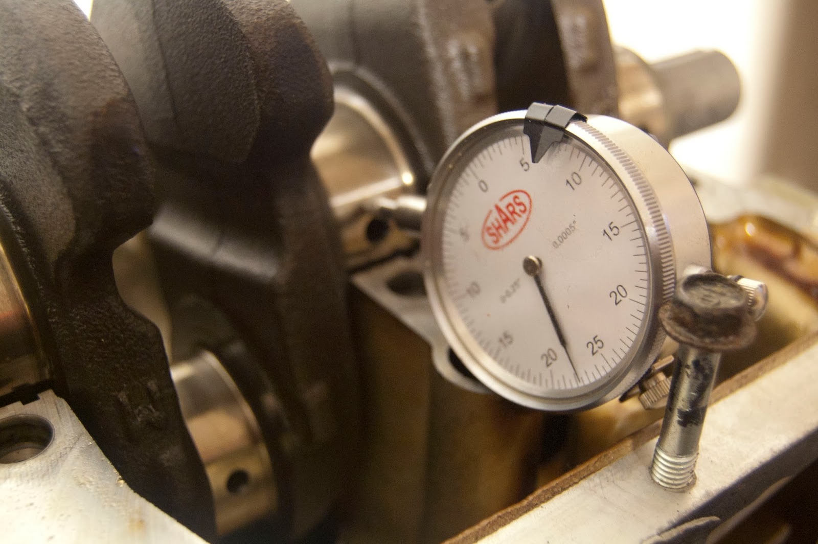
But even mounting the magnetic base somewhere solid didn't work because the setup was too bulky to fit in between the counter-weights. So I ended up taking oil pan bolts and threading them into the block and then fitting the gauge in between the bolts and the crank. This would allow me to keep the crank rotating a full 360 degrees while not hitting the gauge. All I had to do was be sure to keep everything as stable as possible as to not mess up any of the readings.
Per the Acura TSX Service Manual, the maximum allowable run-out specifications are:
Standard (New): 0.03 mm (0.0012 in.) Max.
Service Limit: 0.04 mm (0.0016 in.)
And per my sweet travel indicator, the max run-out I ever saw on any of the main journals was 0.0005 inches, much less than the standard allowable run-out.
Next I pulled the crank out and did a quick visual inspection of the webs on the block and I really freaked myself out.
I saw all of these little cracks around the bosses for where the oil squirters would be placed had this block been out of a TSX and not a CR-V.
Initially I thought that the block was cracked and that my build was done, but the good people of K20a.org informed me otherwise. These are casting marks. They are normal in this place and on this motor, so I felt much better after learning this.
If the block were cracked then I would have been in a bad position. I would have had to scrap it, and possibly restart the whole build with a new block...
And with all of the work I put forth into this already...I would have been kind of devastated. Crazy right? Phew.
This is also a good tool-- a piece of paper:
Diameter in the x and y direction would be measured on each of the journals and recorded on this piece of paper. The difference between these measurements will give journal out-of-round.
Also, I was going to measure the taper of each journal but I decided against it. However for the sake of the reader I have included out-of-round specs and the taper specs included in the factory service manual.
Journal Out-of-Round:
Standard (New): 0.005 mm (0.0002 in.) Max.
Service Limit: 0.010 mm (0.0004 in.)
Journal Taper:
Standard (New): 0.005 mm (0.0002 in.) Max.
Service Limit: 0.010 mm (0.0004 in.)
You'll want to first calibrate the micrometer you're going to use to measure the diameter of the journals. You have to use a 1-2" micrometer to measure the journals on the crank but this short tutorial is just for the calibration of a micrometer.
For any vernier micrometer you'll be able to measure from x inches to x+1 inches. In other words, one micrometer will measure 1-2", another 2-3", another 3-4" and etc.
The micrometers will come with reference points, usually metal sticks or dowels which are machined with a certain certainty to a given length. One of the dowels is shown next to a micrometer in the following picture:
Take the dowel and place it in between the jaw of the micrometer. Tighten the micrometer onto the dowel using the ratcheting mechanism on the end of the tool.
Read the vernier micrometer and write down your measurement of the first dowel. If you don't know how to read a vernier micrometer, I suggest you look at this video for help:
Write down the value of your measurement and the size of the dowel you measured. Then, repeat this step for the second dowel that can fit in your micrometer.
These two values each have an offset due to an error present in the tool. What that means is that although the dowels are precision machined to their own respective lengths, the tool may read a little bit off.
So while in theory the dowels are machined to maybe 3.000" or 4.000" (depending on how precisely they were machined) the tool may read 3.005" or 4.001". And in order to accurately blueprint your engine you need to account for this. Let's make a table and look at the values. It might make you think a bit...and thinking is ALWAYS good!
Notice how the offset decreases with the longer dowel. Let's assume that this is a trend, and not just due to noise. If there were dowels in between three and four inches in length, then we would know for sure whether the offset randomly varied per measurement. However for now, we must assume that the offset decreases as the dowel size increases.
Given that this is a known phenomenon, drift, as it is called, I decided to assume the aforementioned trend was accurate. And assuming the trend is accurate, you can predict how much offset you will get for measurements in between three and four inches using the formula shown at the right in the above picture.
Of course, this technique can be applied to more micrometers than just the three to four inch one. It can be applied to any outer measurement micrometer. Now, if I want to measure a diameter that is, let's say 3.25 inches, then I know that whatever reading my tool gives, it will have an offset of approximately 0.004 inches.
Y = 0.004*X + 0.017
Y = 0.004*(3.25 inches) + 0.017
Y = the offset we are looking for at a measurement of 3.25 inches = +0.004.
So, you get a reading of 3.25", but you know that at this measurement, the offset is +0.004. This means that your measurement is actually 0.004 inches too high. The actual diameter of our theoretical object is 3.21 inches.
If you're still confused about this don't sweat it. As I mentioned it is just an approximation so the likelihood that it is totally accurate is not 100% anyway. If you are still interested however, just leave me a comment and I'll answer your question.
After calibrating the micrometer, I began to measure the diameter of the crankshaft journals. Twice in the x direction and twice in the y direction. Then I calculated out-of-round and entered it into an Excel Sheet. I measured twice to be sure my measurements were exact.
Let's look at the values shall we?
It seems as though, even though some of the measurements weren't repeatable-- probably due to my inexperience-- that the journals were not significantly out-of-round. If they were, then within the service limit the journals would have to be redone. The crank would need to be turned and polished. However this is not necessary.
The next thing to do is to measure the cylinder bores of the engine block. In the Acura TSX Service Manual there are three different heights within the cylinder suggested to measure at...one at the top, one at the middle, and one at the bottom.
Taking your caliper with depth measurement, measure 0.2 inches from the bottom of the cylinder and mark that point with a marker.
Then measure 0.2 inches from the top of the cylinder and mark that point.
Measure the distance between the two marks with your caliper and mark the middle point. These are the three depths that you need to measure diameter of the cylinder bore at in the x and y direction.
Here's how the dial bore gauge looks assembled...look at the circled part:
The circled part is the part that goes into the cylinder bore. The first part of calibrating the gauge is knowing how long this part needs to be. And since it is assembled, it is up to you, the blueprint master, to assemble it properly.
You'll notice that there are four letters on the corner of the deck of the block ("AAAA"):
These letters are each representative of each cylinder bore size and there are two possible letters which may be inscribed on the deck-- A or B. You will be using these cylinder bore sizes to figure out how long the measuring part of the bore gauge must be. Check it out:
Cylinder Bore Size Standard (New):
A or I: 87.010-87.020 mm (3.4256-3.4260 in.)
B or II: 87.000-87.010 mm (3.4252-3.4256 in.)
Service Limit: 87.070 mm (3.4279 in.)
Oversize: 0.25: 87.250-87.260 mm (3.4350-3.4354 in.)
Reboring Limit: 0.25 mm (0.01 in.) Max.
Bore Taper Limit (Difference between first and third measurement): 0.05 mm (0.002 in.)
So, the measuring part must be long enough that when it enters the bore it can compress and give a reading on the gauge, but not so long that it doesn't fit in the bore. To satisfy those conditions I chose 3.4" metal piece:
And I installed a 0.04" washer. This gives me a total length of 3.44" for the sensing part of the gauge.
Then I took my micrometer and I opened it to the size of my cylinder bore while accounting for offset (which I talked about earlier) to be as accurate as possible. I locked the micrometer, and then I clamped it with a soft clamp to a table being sure not to damage either the table or the micrometer.
Then, with the micrometer opened to the known cylinder bore diameter according to my block's deck, I inserted the assembled dial bore gauge and I rocked it back and forth in between the micrometer's jaw.
While rocking the dial bore gauge back and forth, the sensing element becomes compressed and uncompressed and this makes the gauge on the travel indicator move back and forth. At the point where the gauge reaches a stop, that is it moves up, stops, then moves back down, you have your reference point.
This point of measurement is the size of your cylinder bore, and if the cylinder bores are not warped or changed at all from operation then your dial bore gauge should consistently give out this reading.
Take the face of the dial, and rotate it so that the 0 mark lies at this point:
If you're still confused. Check out this video, or leave me a comment and I'll get back to you. This stuff is tricky and it may not come easily the first couple of times you look at it:
Now we're going to begin measuring the diameter of the cylinder bore at three different depths in the x and y direction. Insert your gauge into the bore and rock it back and forth until the gauge reaches its stopping point, similar to how you calibrated the gauge:
Turn the gauge in the y direction, and repeat this step at each of the three depths.
To get started on looking at the results, I made up a little diagram.
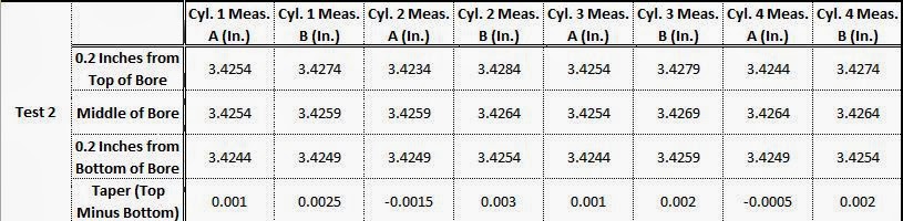
I then measured the cylinder bores and recorded the measurements in Excel. Once for each test:
One thing that I did notice was that the cylinders were worn past OEM spec in the direction of the con-rod force. This is apparently normal according to the thread I made on K20a because the con-rods elongate the cylinder bores.
Regardless though I will need to bore out these cylinders to 87.5 to 88 mm on stock sleeves because they are worn past OEM spec. If they weren't, cast pistons would be an option, but ordering .25 mm oversized TSX pistons and rods brand new would be nearly as expensive or more expensive than some forged options.
Lastly we're going to see if the deck of the block is warped. This step in the process is very simple. It's not too taxing and it's not too technical. You take a big ruler, basically, and you lay it on the top of the block. If the block's deck isn't warped-- that is it is completely straight, then the ruler will have no spaces in between it and the surface of the block, right?
And if it wasn't straight, then you would have spaces in between the ruler and the block. Well, this is where our feeler gauges come in. By measuring the spaces in between the precision straight edge and the block it is possible to determine how warped the block is, if at all.
You will want to perform this process in multiple directions across the deck of the block.
If the block is warped, then the spaces in between the precision straight edge and the block will be greater than these values:
Engine Block Warpage:
Standard (New): 0.07 mm (0.003 in.) Max.
Service Limit: 0.10 mm (0.004 in.)
Let's look at some pics, shall we? You'll notice that I even measured length-wise. This is just to get a little more insight into the shape of the block.
Here are the measurements I took:
And here are the promising results showing that the block is not warped and that all clearances are within OEM spec:
In conclusion the block is mainly in good shape and so is the crankshaft. The only worries I have are about the cylinder bores. Because they are out-of round, I will need to have them bored and honed out to 87.5 mm or 88 mm which are the safest bore sizes on stock sleeves.
Then I plan on running 4032 alloy forged pistons so that I can run tighter piston-to-wall clearances rather than 2618 alloy forged pistons.
Although the 2618 alloy pistons are stronger, they are more ductile and they expand more when exposed to heat. So the piston to wall clearances must be increased.
You can read up more on those choices here. Anyway, for now I'm out. It's been a long-winded and tiring article but I HOPE it offered you a lot of information and made you appreciate the art of blueprinting more. Until next time, keep it chill.