Showing posts with label DIY. Show all posts

Tuesday, June 2, 2015

Race Day Prep: DIY Alignment and Post-Track Day Maintenance

Hello Lexi.Laron readers!  Welcome to another edition of your favorite blog, Lexi.Laron.

On May 13th I took part in my second Track Night in America with the SCCA.  We ran New Jersey Motorsports Park's Thunderbolt configuration yet again.  However, this time, I brought all of my friends after they all read about my first experience on my blog.


After the track, we all headed to Red Robin in Deptford, New Jersey and grabbed a bite to eat.  It was great settling down with friends and talking about all of the cars we raced against that day.  Picture: The Fast and the Furious family dinner.


After a track day, there are usually a couple of things that you do to make sure your car is in working order.  

Firstly, your brake fluid gets really hot.  And like most liquids, brake fluid has a boiling point.

This is why race cars and properly track-prepped cars run DOT 4 fluid and up.  DOT 4 is a good compromise between water solubility and compressibility when compared to DOT 5 and the conventional DOT 3.


Since your brakes get really hot, your fluid gets really hot, and that changes some of its properties.  The most important property to take into account is how hygroscopic, or "water-loving," your brake fluid is.  The hotter your brake fluid gets, the more soluble water becomes in it, thus decreasing its effective boiling point and its compressibility as well.

What does this mean?  It means mushy, soft brakes.

Secondly, you're supposed to change your oil.  Here's what my oil looked like after two track days and 2,000 miles of driving:


Needless to say, it was pretty black.

And in addition to all of that, I had a number of other things to take care of-- including a new clutch master cylinder, clutch slave cylinder, tie rods, and camber bolts.  Expect some sweet DIY's soon!


The new tie rods and camber bolts are being installed because I have been riding with an insane amount of toe in and negative 0.7 degrees of camber on one side of my car and negative 1.7 degrees of camber on the other side of my car!


This is due to a couple of reasons.  For one, the DC5's struts were designed so that the tie rod connects to them instead of to the upright, like on most cars.  You can see it in the picture below:


As a result, when aftermarket manufacturers go to make coilovers for these cars, sometimes the placement is not perfect.  Throw in a lower ride height, and the fact that there is play in between where the coilover connects to the upright, and you get finicky camber adjustments on a bulky, FWD car.

Another side effect is the fact that the stock tie rods will not have enough thread or they may be too short to accommodate the car's drop and the desired toe value.

Luckily for us DC5 owners, there are yet MORE aftermarket options to correct these pesky problems.  See exhibit A below for further reference:

Exhibit A

The first piece of the puzzle are these Da Vinci Designs (DVRace.com) Tie Rods made by Todd from ClubRSX.  These tie rods are "adjustable" but not in the way that most people are used to tie rods.

These tie rods actually are modified OEM units.  The threaded part of the OEM tie rod is cut off, and a bolt is welded onto the end of the tie rod.  Then, a long, threaded, metal dowel is inserted into the bolt.


You see, with this setup, even if you thread the tie rod end ALL the way onto the dowell with this setup, you can still spin the dowel itself into the tie rod, allowing you even MORE adjustment than simply cutting more threads into your tie rod as shown below:


In addition, if you take notice of the picture shown above, you will also notice that cutting threads further into an OEM tie rod may actually be dangerous.  When you cut threads this deep, you are actually cutting into a part of the tie rod that is thinner, and although your tie rod may not fail in reality-- this is always one surefire way to increase the likelihood that it will fail...

The next piece of the puzzle is a set of camber bolts which go through where the coilover meets the upright in the front of the car.


Here's how camber bolts work:

Image from H&R

The bolt has an eccentric "lobe" much like a camshaft has lobes that control the valve motion in your cylinder head.  As you turn the bolt while it is holding the strut to the upright, the lobe controls the angle at which the upright sits-- thus changing camber angle.

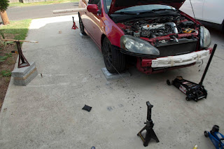
After installing all of my parts, I broke out the jack stands and did a string alignment.


For starters, you're going to want a level surface.  Based on previous experience, I know that if I want to achieve a level surface on my driveway, all I have to do is take four 16" by 16" concrete blocks, one for each wheel.  Then, I put one tile on each of the concrete blocks for the rear wheels.


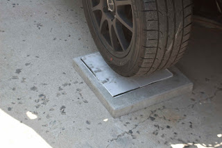
To create a "frictionless surface" otherwise known as "toe plates" I take two lineoleum tiles and place them face to face with some grease in between them.  Then I lay the two plates under each wheel.


Since my rear alignment was done by Lykon Automotive in Levittown, PA (THANKS TYLER), I didn't have to touch it.  The rear alignment is set at zero degrees of toe and negative two degrees of camber.

Therefore, I moved to the front, where I would set my specs to zero degrees of toe, and negative three degrees of camber.  To start out, I simulated the weight of me in the passenger seat with some cement and gravel bags and I locked the wheel in place using zip ties and a piece of wood.


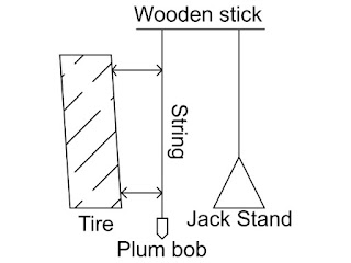
Then, I set up a vertical reference next to my wheels.  Doing this allows me to measure my camber with a tape measure and some good old math and trigonometry.  To make my vertical reference, I used my good friend gravity!  Yes, I'm a nerd...but I'm a cool nerd with a racecar.


Here's a diagram of the setup:


If you measure the distance from the top of the wheel to the string and the distance from the bottom of the wheel to the string you can start to form a right triangle, where the diameter of the wheel is the hypotenuse.  

Notice that the difference between the top string and the bottom string is the length of the top part of the right triangle.


The hypotenuse is 16", and you can find the difference between the top and bottom by using the tape measure, so all you have to do is use an inverse sine function to find the value of your camber angle:


This may seem complex, but any regular scientific calculator can perform this function


After my first measurement, I discovered that my camber was at negative 3.8 degrees.


So, I had to adjust my camber bolts to get the desired camber angle.  To make adjustment easier, I removed my windshield washer fluid reservoir and got a 17 mm socket on a 1/2" wratchet and started turning the eccentric bolt.


After I got the desired camber on both sides of the vehicle using the aforementioned method, I took the wheels off and while holding the eccentric bolt in place, I tightened the nut holding on the eccentric bolt as tightly as I could by hand.


After setting camber on an alignment rack, you are normally supposed to set the toe.  So, following convention I decided to do so.  For toe, there is a commonly employed method by many grassroots racers known as a "string alignment."


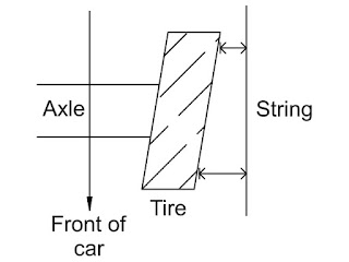
You take two jack stands and some string, and you align the string to the "geometric center" of the car...much like an alignment rack can do for you automatically.


For a car with equal track widths front to rear (like my car) this is easily done by measuring from the center cap on your wheels to the string which spans the length of the car.


Once the distances from both center caps are equal on the front and rear of one side, move to the other side of the car and repeat the process.

To check toe, all you have to do is take two measurements on each front wheel-- one measurement at the front of the wheel and one at the rear.


Then you take note of the measurements.  It's simple.  If the front of your wheel is further from the string than the rear is, you have toe in on one side of your car.


If the distance between the front of your wheel is closer to the string than the rear is, you have toe out on one side of the car.

After you figure out what your toe setting is, you can spin the tie rods the way you need to spin them to get the desired toe.  This was a snap with the Da Vinci Tie Rods from Todd.  Thanks Todd!


After I finished my alignment, I set everything down and took the car for a drive.

Here are the final results for my alignment:

Front
  • Camber: -2.9 degrees
  • Toe: 0 degrees
Rear
  • Camber: -2.0 degrees
  • Toe: 0 degrees
With how much the car rotated on my previous track days, I can only imagine how much more the car will rotate for my next event.  Couple that with the new tires I bought...and well...we'll just have to see how I do ;)


Thanks for reading guys.  I hope you found this post as useful as my other ones!

Peace!


Sunday, March 30, 2014

PLM Header Review and Install

Hey guys and gals.  Welcome to another installment of Lexi.Laron.

For those of you who don't know, I've been rocking a shorty header for years now.

OEM Header on the Left and DC-Sports Shorty Header on the Right

And although it has served its purpose and it provided me with some mild gains on the so-called "butt dyno" and even allowed me to keep my catalytic converter setup intact, a shorty header is ultimately not comparable to a race header in terms of performance for the RSX.

Typically a shorty header will provide a good alternative for those who wish to keep their catalytic converter and to do a quick, cheap bolt-on which will give them a slight bump in power.

A race header, often times deletes the cat, however it has much longer and much more gradual tubes coming off of each cylinder, resulting in smoother flow.  The race header provides better low to mid-range torque and power versus the shorty header which will typically provide better high-range torque and power.  

Check out this site to read up more on this topic if you're still curious.

So, given all of the positives associated with running a full-length or "race" header, I decided to reach out to a reputable brand known well in the RSX community for making quality products at affordable prices...


Private Label Mfg. or PLM was kind enough to send me one of their headers for the RSX Type-S, and so I decided I would do a review to share with the RSX owners of the world.


When you open up the box from PLM you will get a couple of things.  For starters, you will get the upper part of the manifold with the flange that bolts up to the engine, two collectors which slip-fit onto the upper part of the header, a collector which slip-fits onto the two aforementioned collectors, and finally a test pipe which bolts from the header to the exhaust.

Here is the top part of the header:


The top part of the header looked remarkably well constructed with gradual bends leading from the engine to downstream where the collectors would connect.


And the insides of these runners from the head of the engine to the exhaust also looked smooth.  Here are pics of the welds on the outside:


From the top part of the header, there are two collectors which merge the exhaust flow from the upper four tubes into two tubes.  This is what the first of the collectors looked like:


And here are some detailed shots of the welds on the first collector:


Here is the second collector:


And here are more pictures of some wonderful welds from PLM!


You take the two collectors that I just showed, and you slip-fit them onto the top part of the header.  The bolts that you see hanging off of the welded on sleeves are used to squeeze the slip-fit sections of the header together.  When all is put together, these sleeves allow bolts to "seal the deal" so to speak.

After you bolt up the two collectors you'll have to bolt up a third collector which will make your header look a little something like this (I have circled the slip-fit connections):


Now, let me say that this third collector is a piece that I walked around with all day on Monday looking for the right bolts to connect this to the test pipe with.  And all the while, I was getting a TON of compliments on the welds and construction of the pipes I was hauling:


Let's take a look at where the two pipes which merge the exhaust gases toward the primary O2 sensor are welded together.  You can see that the welds are meticulously dimed through and it's not just this pipe that is like this...it's the whole header.


I was a huge fan of the thickness of these flanges.  The thickness of ALL of the flanges allowed me to really torque down the connections for this header to make it completely leak-proof.


Here's the test pipe I was carrying around on Monday:


Everyone from muscle car guys to import guys was telling me how well-constructed these pieces looked.  They were practically excited for me without even knowing what car I was bolting this to!  That's how you know car enthusiasts share a strong bond...whether they drive a tricycle or a t-rex (if you know what I mean hahah).


Here's where the test pipe accepts the donut gasket and bolts up to the collector.  Again, look at the nice, thick flange:


And with the included gaskets, PLM made my life a little easier when it came to installing this piece, right?


The next step after unboxing the beautiful set of stainless, welded pipes was to get the beautiful, dirty RSX up in the air.  Sorry Arcie!  I'll give you a bath soon!


After getting under the car with a cutoff wheel and a Dremel for the hard-to-reach spots I started cutting off old bolts that I couldn't break off with an impact gun.


I decided to remove my whole exhaust so that I could get rid of any existing leaks by cleaning the faces of all flanges and replacing all gaskets and bolts.  To start, i took off the mid-pipe:


While I was in Wisconsin, I tried to fix an exhaust leak where the mid-pipe met the resonator, however I couldn't get the bolts off with hand tools and I didn't have access to power tools, so I just covered the leak with some RTV sealant until I could actually fix the leak:


After removing that monstrosity of a problem, I moved to where the flange of the muffler met the flange of the resonator and began to remove those bolts:


Then I removed the downpipe and catalytic converter combo pipe by popping off the spring bolts that held it to the old shorty header:


And I used THIS to do it:


Voila!


Moving around to my engine bay I started to remove the bolts that held the shorty header to the cylinder head:


With all of the exhaust components off I trudged on:


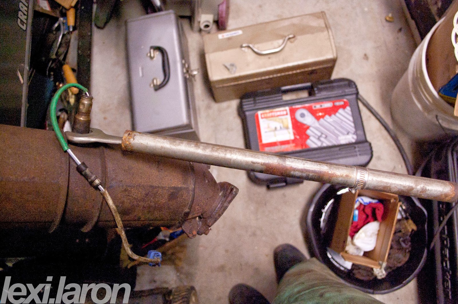
Clamping the downpipe/catalytic converter pipe into a vice would allow me to remove the O2 sensors, but first I had to get the proper tools.

Here is a pic of the downpipe clamped up:


With the downpipe clamped up, I opened up my Dad's box of special, extremely thin wrenches to use to remove my O2 sensors:


I then grabbed a rudimentary piece of pipe and used it as a cheater bar for both the primary and secondary O2 sensors.  Aren't I a cool guy?


Then I started cleaning all of the flanges for my exhaust.  Doing this allows the mating surfaces to come cleanly together from pipe to pipe.  You put your gasket in between the two flanges and I put some RTV sealant on the gasket before putting the gaskets on to be extra sure I wouldn't get any leaks, and having a clean surface to do all of this with is extremely important.

Otherwise the RTV sealant wouldn't do a thing, there would be uneven spots on the flange, causing the gasket to not sit flush, and ultimately it would make the exhaust sound like crap.


And I laid all of my exhaust parts out after I finished cleaning them:


Then I matched up the exhaust gasket for the new header with the test pipe on a vice:


And I got some anti-lock cream from Denso and I put it on the secondary O2 sensor's threads and put it in the test pipe:


The primary O2 sensor from the 05-06 RSX Type-S is a narrowband O2 sensor.  This means it basically works as a dummy sensor which tells the computer if the air-fuel ratio is about 14:1 at idle and cruising conditions, and if the ratio is not, then it adjusts the trim on the fuel injectors and ads or removes fuel as necessary.

A wideband O2 sensor has a wider operating range and can read a larger range of air-fuel ratios, so it's better for tuning because you can see what your air-fuel ratios are at no throttle, part throttle, and full throttle-- allowing for a more exact tune.  In fact, if you run KPro, you must have an 02-04 RSX Type-S primary O2 sensor.

Check out this source for more info.


Now that we've sufficiently covered all of the unexciting stuff, let's move back onto the header.

Let me again reiterate how satisfied I am with the quality of this header.  After admiring it, I banged together the slip fit connections with a rubber mallet and tightened them up.  It went fairly smoothly except for the slip fit where the last collector with the primary O2 sensor bung is.  I'll show you what I mean later.

Here are the first couple of slip fit joints going together:


As I mentioned, the last slip fit connection did not go together perfectly, but it's okay because I just tapped it with a rubber mallet and it all came together well.  Here's what I'm talking about:


But after some persuasion, the header was looking gorgeous:


Then i got under the car and unbolted the sway bar so I could slide the header up in there.

Note that if you take this route, you will most likely want to wait to install the last collector that I had a little trouble with that has the primary O2 sensor.  That way, you can swing the sway bar up and over the header back into its normal position before bolting the exhaust back on.

It will also save you HOURS lost due to having to remove the header AGAIN to put the sway bar back on.  Can you tell I had some trouble with this??  LOL.

Anyway here's me removing the sway bar:


After bolting up the header using the OEM header bolts and the gasket provided by PLM I got under the car and got to installing the primary Denso O2 sensor.  Here's the welded on bung on the collector that leads to the test pipe:


I got some Denso anti-lock cream and put it on the threads of the primary and screwed it in there, clipping it into the proper spot on the RSX's harness:


If you read through forums, there are tons of people who complain about melting their O2 sensor wires due to an incorrectly installed race header.  However, if they were worried about melting the wires, then they should have installed it correctly the first time.

To prevent this from happening in my case, I zip-tied the wires for the primary and secondary O2 sensors to OEM brackets after I wrapped the wires in multiple layers of insulation.  This would hopefully provide enough distance between the O2 sensors and their wires and enough protection for their wires as well.


After getting the exhaust bolted up I went and grabbed my test pipe to bolt up too.  You're going to need some pretty long bolts for where the collector bolts up to the test pipe at the donut gasket.  I believe I ended up using M10 or M12 x 1.25 bolts which were 70 mm long.  I then had to run the bolts through a die to make the threads proceed further down toward the hex-shaped head of the bolt to further ensure I'd have enough clamping power for the two flanges.

This is another place where PLM's quality really shined.  I tightened these flanges as much as possible and I swear I would have broken the bolts before I bent these flanges because they were so thick.  Good call PLM.  I approve!

Here are some pics of the bolted up test pipe with the secondary AND primary sensors now all secured to the car's OEM brackets:


Here's the insulation I added to the secondary one-- hope it holds up:


As you can see, installing a race header-- ANY race header-- is a lot of work and time for the average guy like me.  I'm no mechanic and there are people out there who do this for a living or who have been working on and modifying cars for years like my buddy Josh from N-Spire Performance.

Yet that's what I love about stuff like this.  When you're all finished installing something on your car, the end result is what I love to see.  And with this header, the sound of the car is now amazing and so is the feel of it.  Take a look at some of these sound clips!

Here's a sound clip of me bouncing off of the rev limiter (around 5000 RPM's for 05-06 Type-S's) with my old setup:
  • DC Sports Shorty Header
  • OEM Catalytic Converter and Downpipe
  • A'PEXi GT Spec Cat-Back Exhaust
  • AEM Short Ram Intake
  • Stock K20Z1

And here's a sound clip with the new setup!  It's much deeper in the low range and it has a raspier sound from around 2500-4000 RPM's that sounds A-MAZING.

  • PLM Race Header
  • A'PEXi GT Spec Cat-Back Exhaust
  • AEM Short Ram Intake
  • Stock K20Z1


Overall I am EXTREMELY impressed by the quality of this product, the results it provided me, and with PLM's courteous customer service.  

PLM was very friendly when I contacted them about this opportunity and I got my product in no time.  If you ever come in contact with Frank from PLM, know that you are in good hands.

The welds of this header are all high quality welds that would make most automotive enthusiasts very happy.  The fitment is great.  And the design that went into the flanges can't be beat.

I feel like the car is more powerful in the low and mid-range, however I did not expect to feel as much of an improvement when "VTEC kicked in yo" as I did.  It feels like I gained power all throughout the powerband, and the sound DEFINITELY does not fail to impress.

Thank you for reading this article, and I sincerely hope that my experience has been helpful to you.  Maybe you too will decide to go with this great product!

Thanks for reading, have a good one people!